• Welcome to H4O! For a reduced ad experience, please login or register with the forum.

A K5 Cummins Conversion: The saga continues...

MaxPF

AGNTSA
Messages
1,394
Location
The dark side of the globe
During the last nail-biting cliffhanger, I had to get an 8 lug rear axle to complement my brand used D61 front. I could have re-geared my existing 14bsf, replaced the 6-lug shafts with 8 lug units, threw on 8 lug drums, and headed down the road (metaphorically, at that point). However, I have a mental block when it comes to having a rear axle with a smaller R&P than the front.

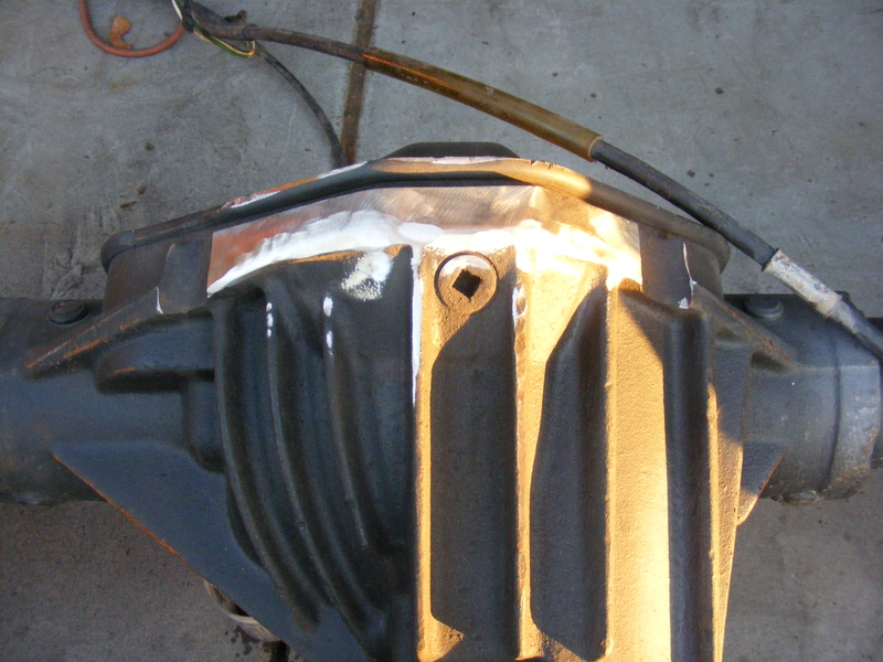
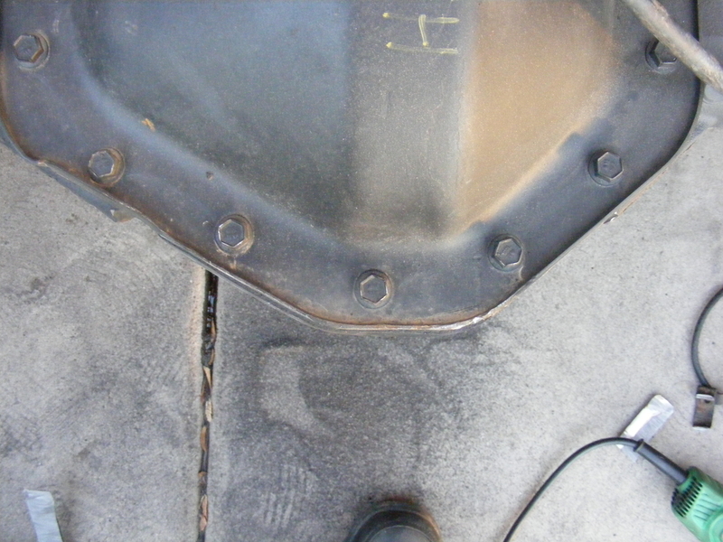
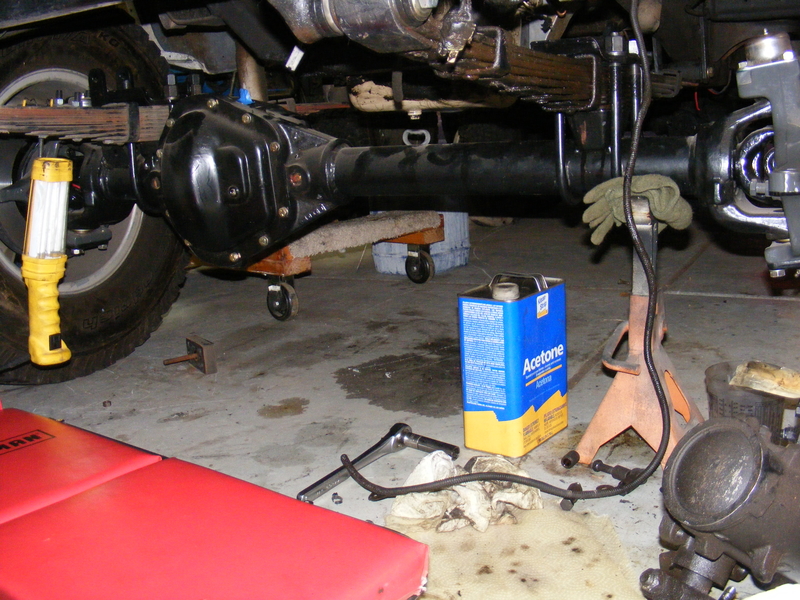
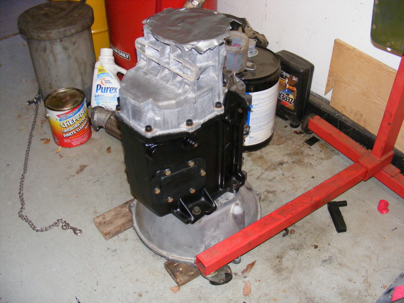
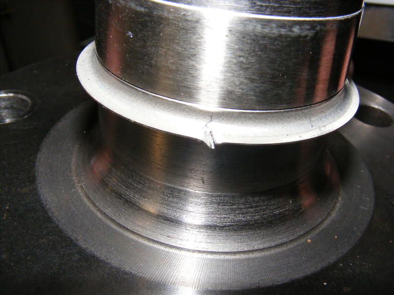
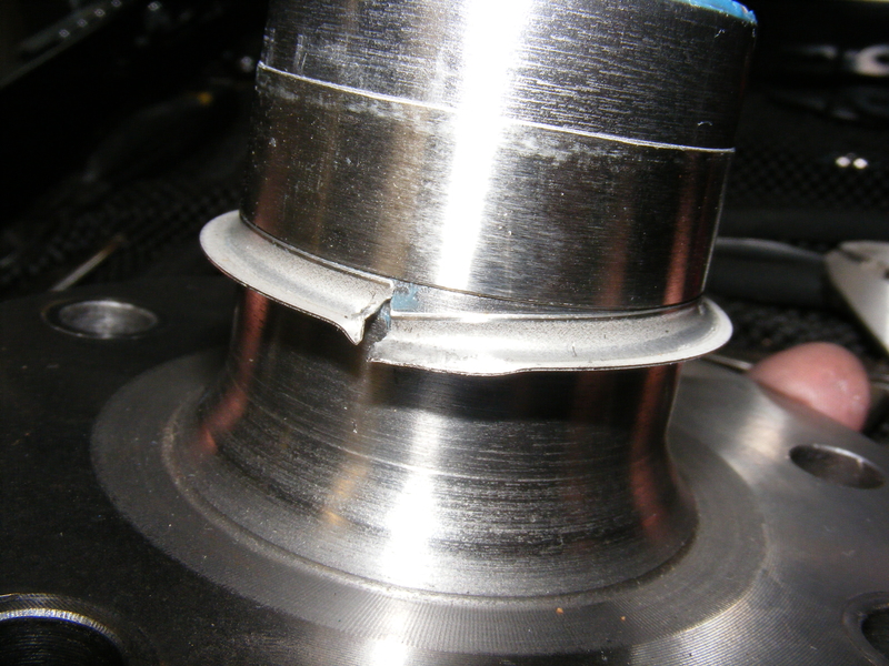
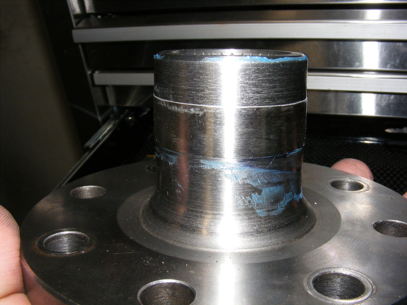
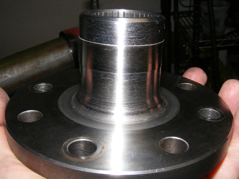
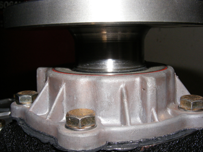
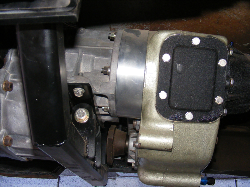
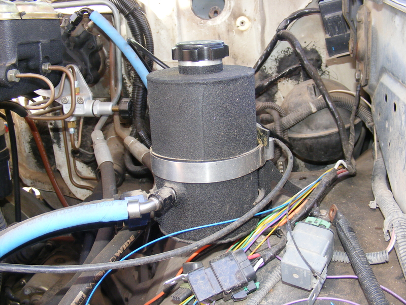
With that, my ultimate choice was boringly predictable: I got a 14bff. In this case, it's a 2003 AAM 10.5" 14bff with disk brakes, 4.10 gears, and a gov-bomb diff. The first thing I did was shave the bottom to hopefully reduce the number of the dreaded code 14's:

r-DSCF4315.JPG


r-DSCF4317.JPG


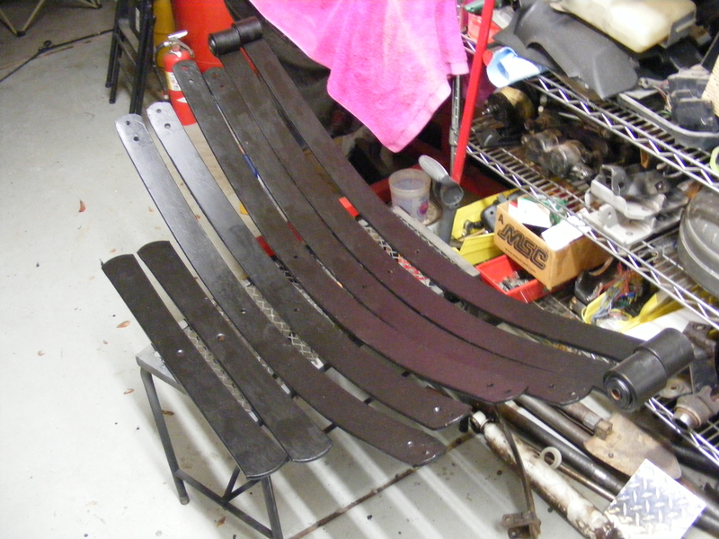
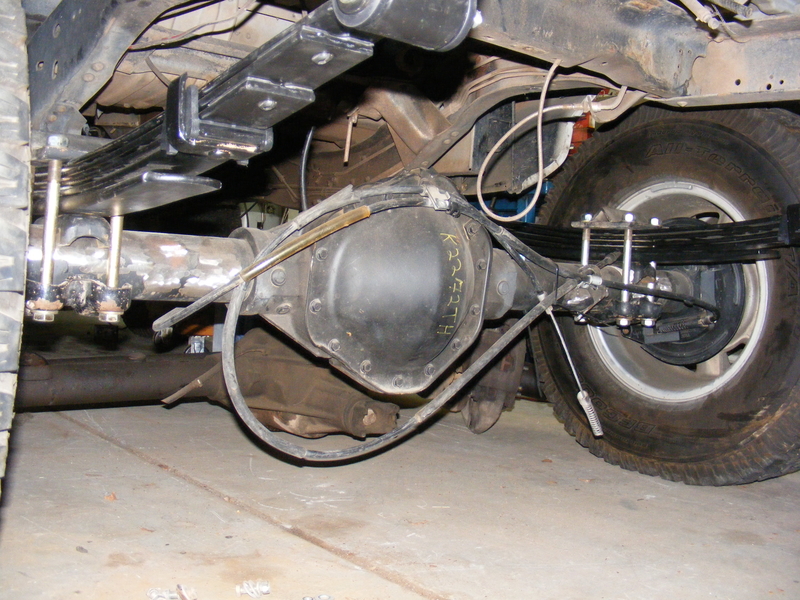
After that came the usual :hack::grind::weld: to relocate perches and add new shock mounts. Before I slung the axle up under the truck I had a couple other things to do. First was rebuilding the rear spring packs:

r-DSCF4336.JPG


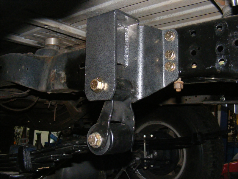
Then replacing the echobit flips with regular bolt-on flip brackets. This required liberal use of the air chisel, which makes the neighbors oh-so-happy :giggle: The result was this:

r-DSCF4453.JPG


r-DSCF3191.JPG


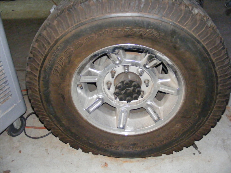
So now I had axles, springs, and mounts ready to go, but I still needed 8 lug wheels with a minimum of 16.5" diameter to clear the rear calipers, along with tires on said wheels. For that, Craigslist came to the rescue. I found a guy selling a set of just what I needed:

r-DSCF4355.JPG


Yup, good ol' H2 wheels with good BFG Mall Terrains. Guy was asking 6 bills, but I chewed him down to 4. Or, more precisely, his wife made him take the offer of 4 in order to get the tires out of the garage :giggle: You shoulda seen what he replaced the perfectly good factory wheels and tires with on his poor H2 :barf:

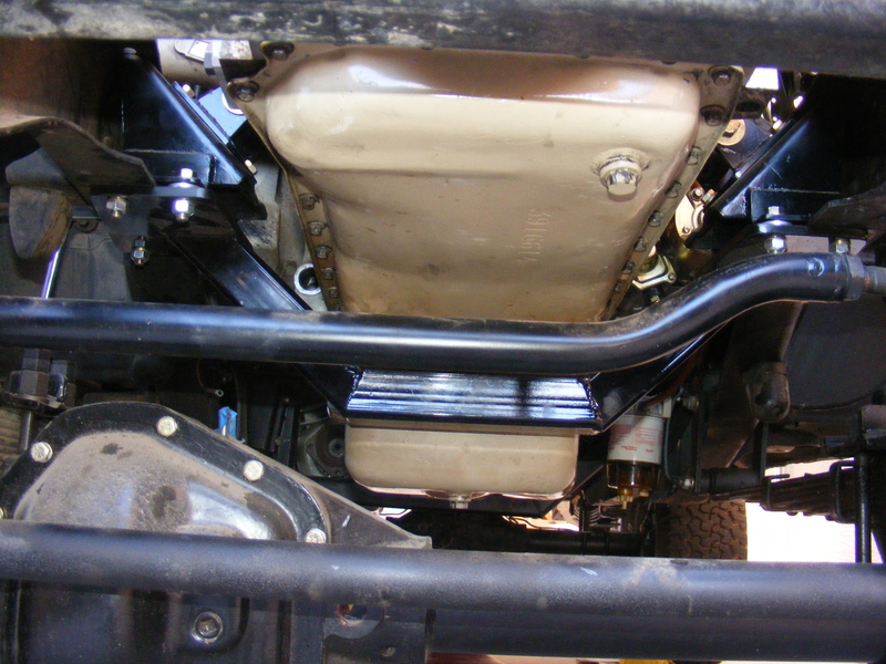
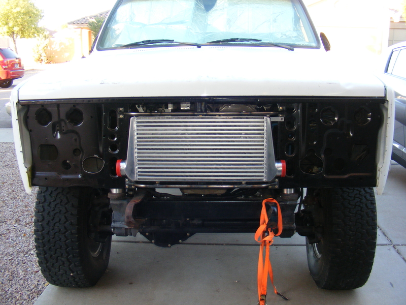
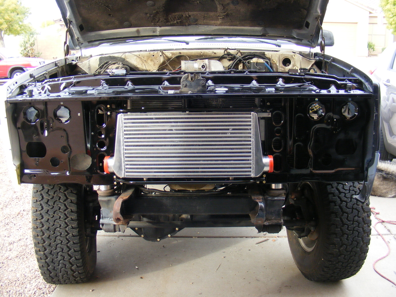
With that last piece of the puzzle fit I can finally get the truck resting on tons:

r-DSCF4451.JPG


r-DSCF4452.JPG


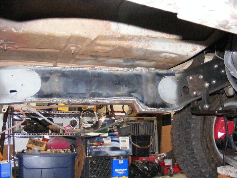
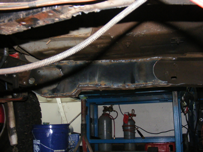
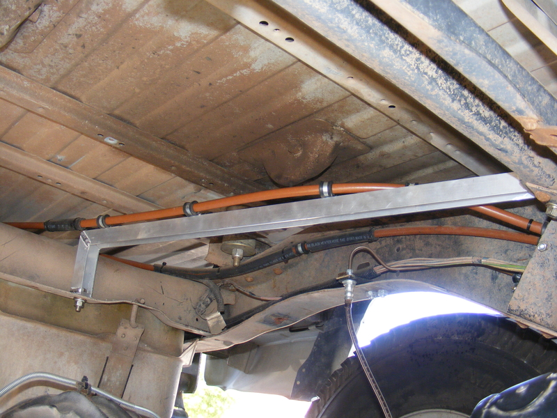
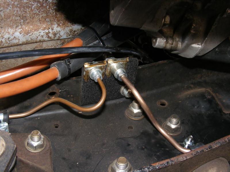
So far, so good. Now, if you read the whole drama thus far you recall that I had replaced the entire front section of frame with a 1-ton section due to massive cracks in the steering box mount area of the original frame. After a year and a half or so the new 1 ton frame was showing no signs of fatigue around the box mounts, but I wanted to make sure it would NEVER be an issue. The usual method of prevention on a stock frame is a bolt-on brace from outfits like ORD, but my removal of the original crossmembers (and reluctance to buy stuff I can fab myself) made that no longer an option. The second method is boxing in that section of frame. That is the route I chose, and it was made easier and better by the non-stock crossmember that I added which would tie everything together.

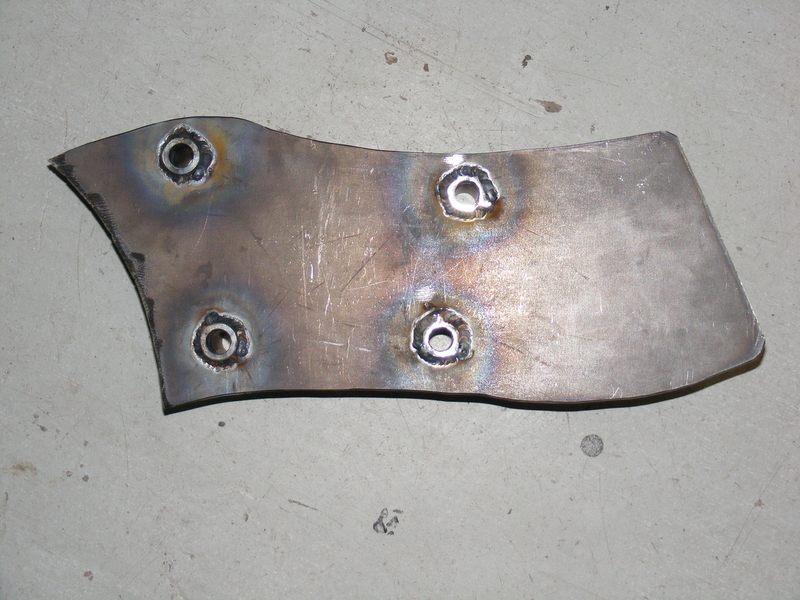
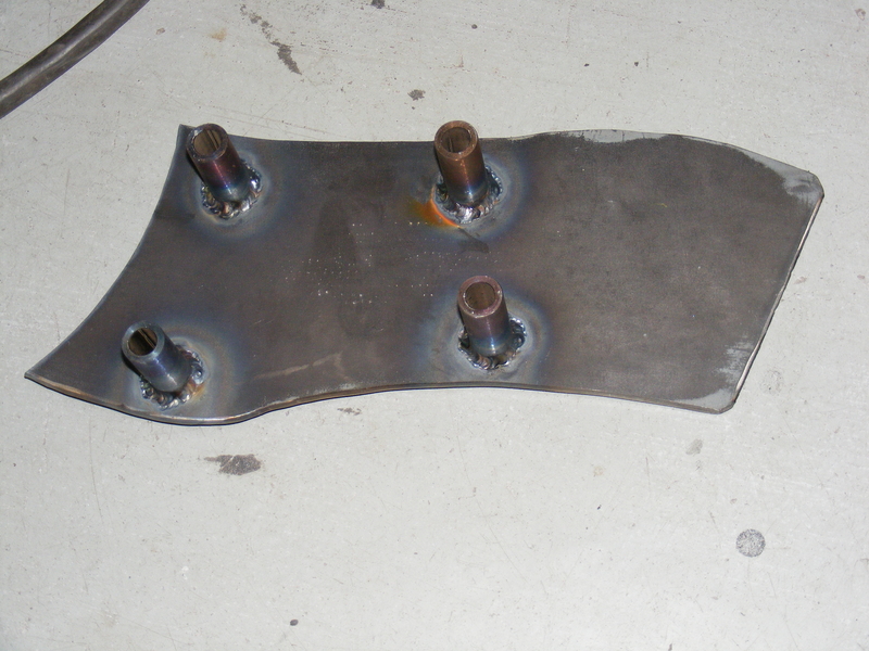
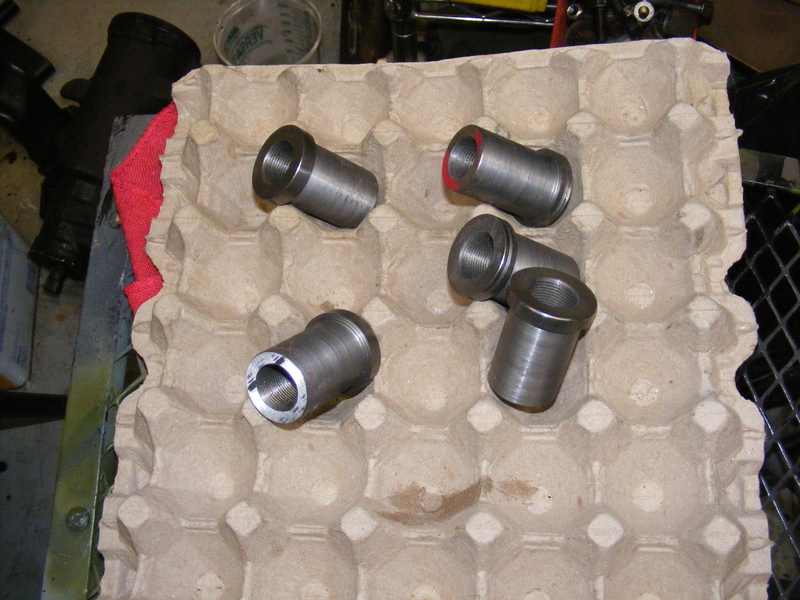
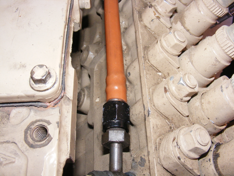
First step is to trace out the pattern and cut it out of 1/4" steel plate. Then clamp the piece inside the frame and use a drill bit to transfer the box mount hole locations to the plate. Drill out to 3/4", put in the frame, add spacer sleeves, tack, remove, weld sleeves, and you have this:

r-DSCF4459.JPG


r-DSCF4460.JPG


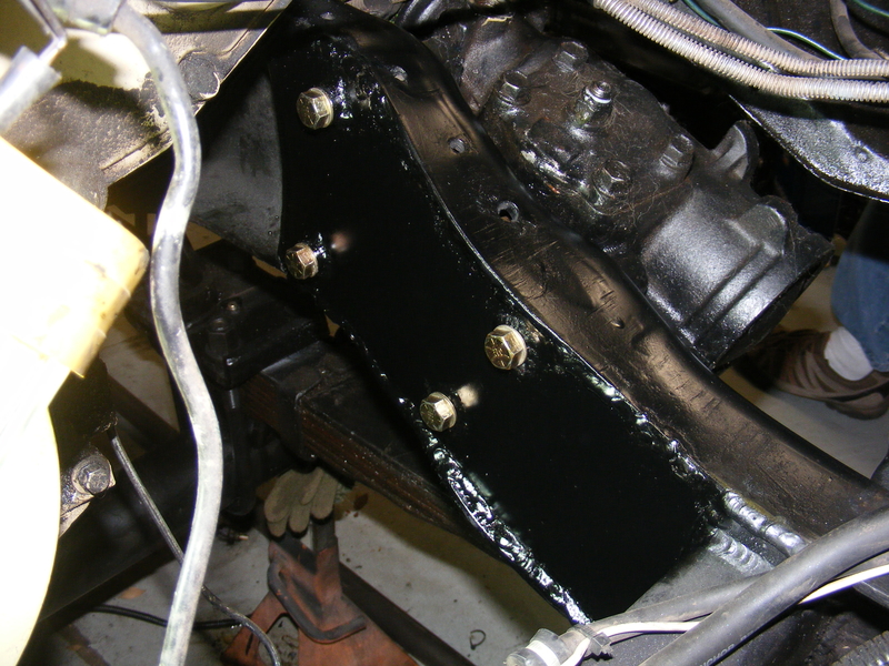
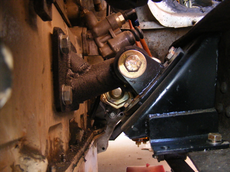
After thoroughly cleaning the frame area where the plate will weld in and spraying both it and the plate with weld-through primer, it got welded in, painted with chassis paint, and the box bolted up:

r-DSCF4461.JPG


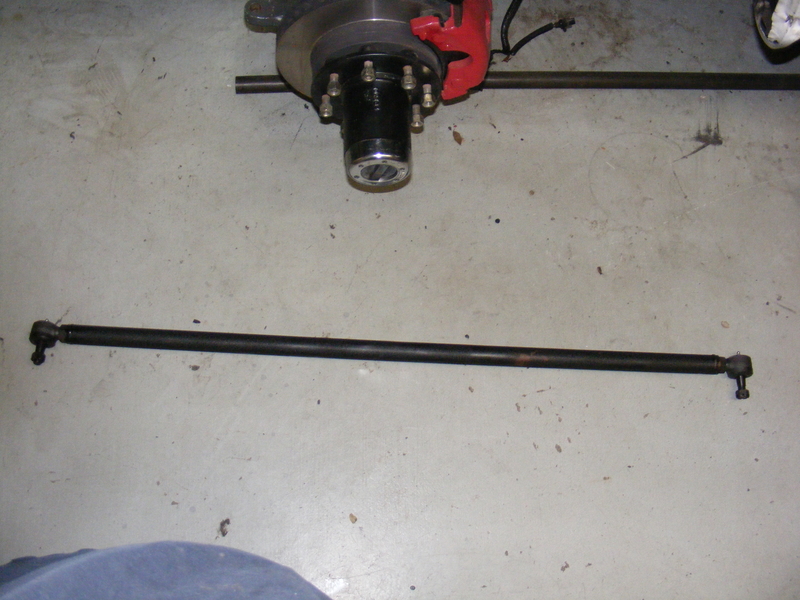
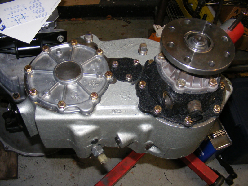
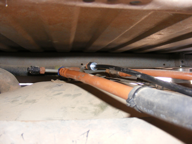
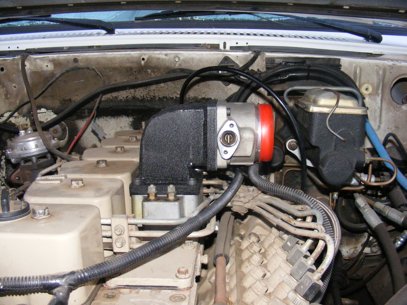
My truck, like all solid axle 4WD GM trucks, originally had push-pull steering. Mine worked fine until I moved my axle forward 2 inches, which shortened the already short stock drag link by the same amount. Now it had serious issues turning when flexed, and had developed bump steer :( 
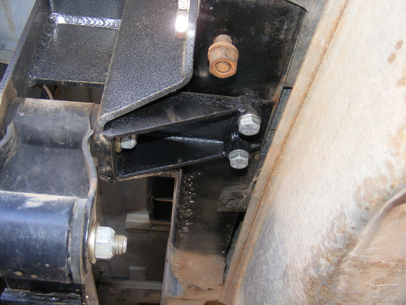
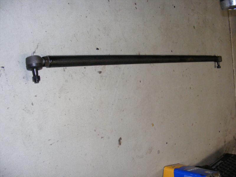
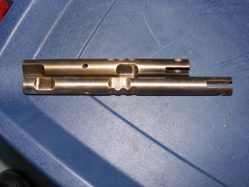
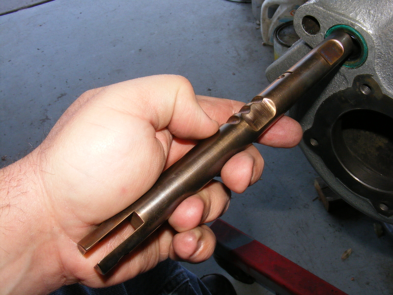
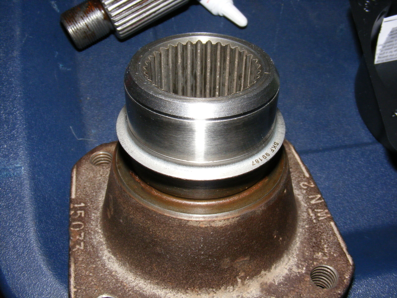
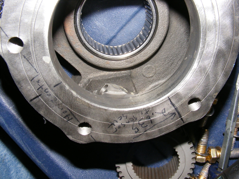
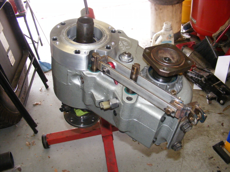
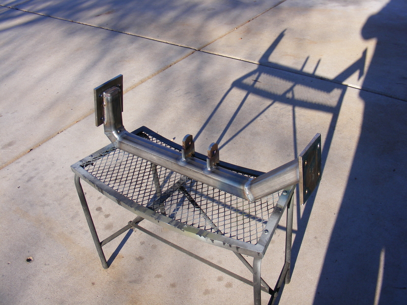
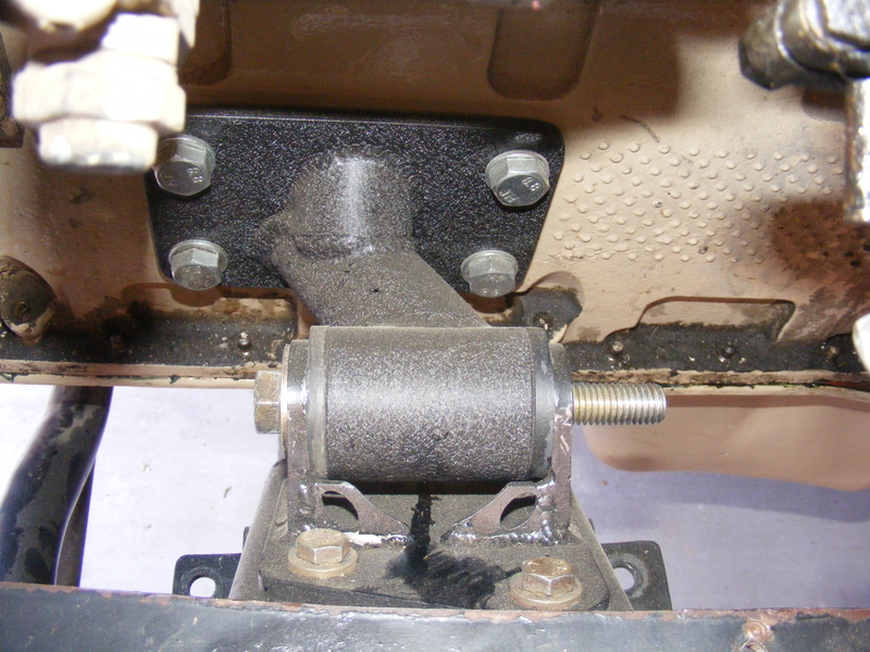
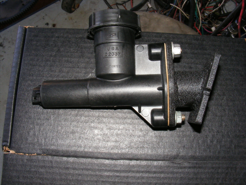
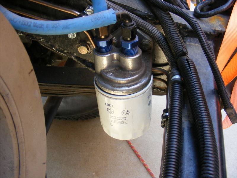
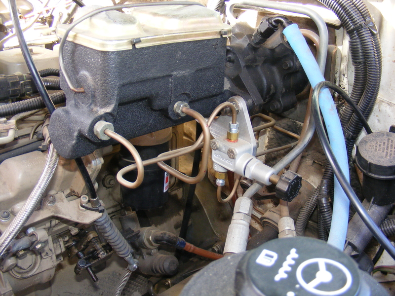
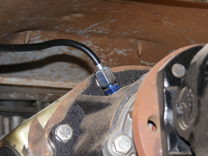
This sucks, so I was going to convert to crossover steering, which requires a box with a 2WD sector shaft. By this point I already had new tie rod and drag link ends from Parts Mike, as well as a 2WD box and suitable Pitman arm from a friend. I also had a stick of 1-½" .120 wall 4130 tubing and these parts that crawler made:

r-DSCF4457.JPG


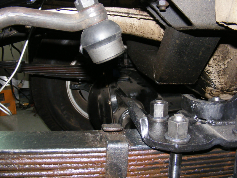
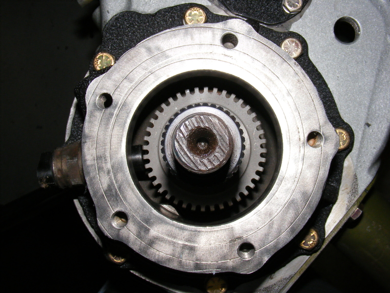
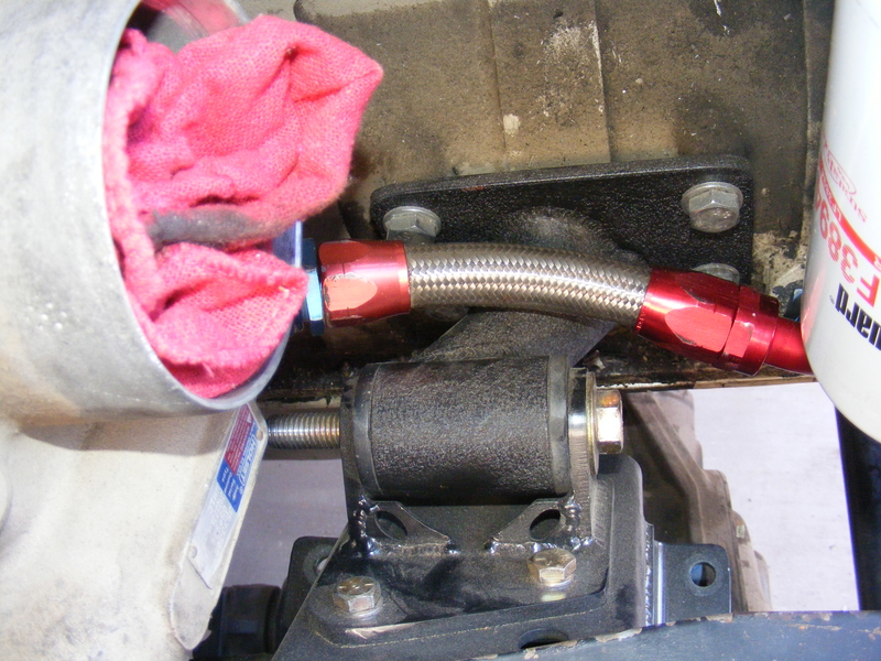
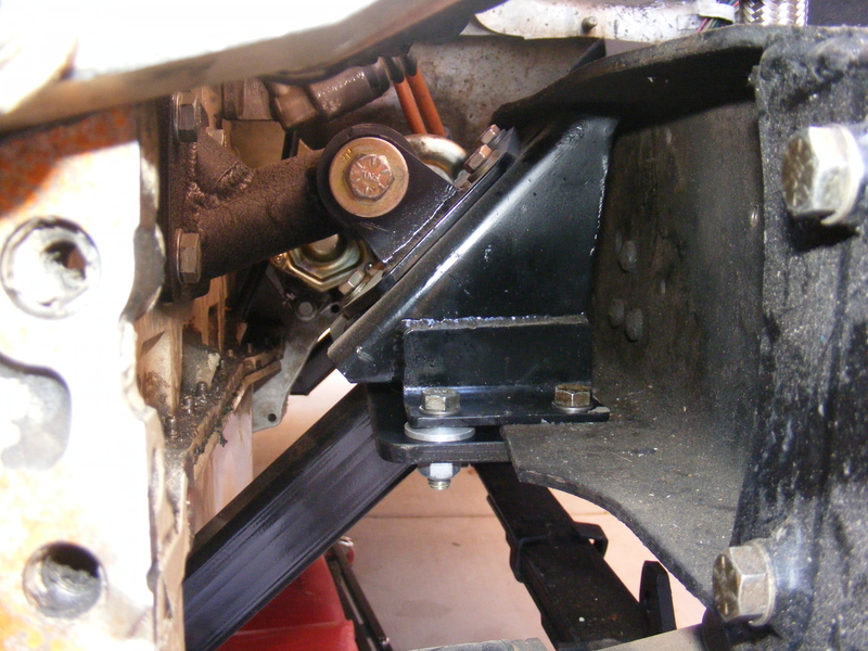
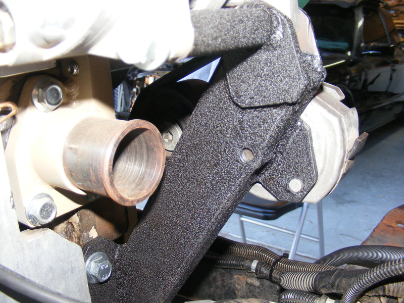
With the box bolted up, I installed the Pitman arm and temporarily installed a DLE to check stuff out. Hmm, looks kinda close :huh:

r-DSCF4462.JPG


r-DSCF4463.JPG


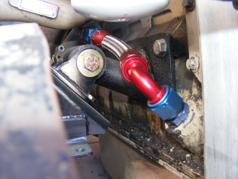
A quick cycling of the box confirmed that the DLE mount bolt clears the frame (BARELY!). As for the clearance between the spring and DLE, that will require bumpstops. Eventually. In the meantime, there's no danger of contact with my truck holding down concrete :giggle:

That's it for now. I would come up with something witty, but I'm too tired, so I will stick with "Stay tuned." :shifty:
 
Last edited:

MaxPF

AGNTSA
Messages
1,394
Location
The dark side of the globe
OK, so I got axles in, Yay... But I still can't even roll the truck forward because I don't have a tie rod to keep the front wheels straight. Well, remember those built-by-Todd parts in the cardboard egg tray in the previous posts? They just happen to be ⅞-18 right and left hand tapped bosses for building tie rods, drag links, and Panhard bars. I combined one right and one left with a suitable length of 1-½ .120" wall 4130, some TIG welding, a coating of wrinkle paint, and some tie rod ends from Parts Mike end ended up with this:

r-DSCF4464.JPG


r-DSCF4465.JPG


Now that I had a rolling chassis again, I could address the next item: a transmission. I was originally going to run an Allison, and even had one built and ready to go, but I sold it to someone who needed it worse than I did (and paid plenty of money for the turn-key kit). Then I brought home an Eaton-Fuller FS-6406. I got it for a good price, and planned on throwing OD gears into it, but it was just too much trans for a Blazer. A one ton truck that tows a lot (and routinely breaks NV5600s and G56's), yeah it's the hot ticket, but a 365lb 6 speed is just too much gearbox for a K5. I would have to substantially surgically alter the floor and firewall to accommodate the trans, and i just didn't have it in me anymore. So I sold it off to a guy who actually needs it for his dually on 37's.

I still needed a trans, and there was only one practical choice. The problem is, I don't like it. I'm talking about the NV4500, and anyone who knows me knows I hold this trans in very low regard. The first through fourth gear portion is decent enough (although the 465 is better IMO), but fifth gear is a complete crap design, and the gearbox has smallish countershaft bearings. OTOH, it can be fixed up and it has the OD I need, so it's what I ended up with if I ever want this heap to roll under it's own power again.

Because I wanted to run a round pattern 205 that I already have, and it has a GM bolt pattern and GM 32 spline input, I chose to run a late GM NV4500. Parts are interchangeable with the Dodge version, which allowed me to run the aftermarket 1-⅜" input shaft designed for hot-rodded Cummins apps. I found one for sale from a guy on 4BTswaps for a good price. It was out of a 350 Vortec truck, so it had no mainshaft damper but a spacer sleeve instead. Not a big deal, but the damper was put on the units that went behind the 4.3 V6 to keep gear rattle down, so I expect I may end up with some gear rattle. We shall see. Anyways, here's the trans in pieces:

r-DSCF4390.JPG


r-DSCF4394.JPG


r-DSCF4396.JPG


If you look at the following pic you will see that the end of the countershaft has 16 wide-spaced splines in it. The shaft can accommodate 48 splines that size, but New Venture chose to only run a third of the maximum. Why? I dunno. SInce the input-to-countershaft multiplication is something like 1.8:1 there is a LOT of torque applied to those splines when at full throttle, even in a gas motor. That they survive at all is a miracle.

r-DSCF4395.JPG


Usually, it is the mainshaft gear that has issues. It's small and retained with a spanner nut. Over time the torque can work the gear back and forth, eventually working the nut loose. The nut backs off and the gear follows it, walking off the splines. There are numerous fixes, but my favorite is this. Unfortunately, they only make that lock for the Dodge 29 spline shaft, so I used a piece of female 32 spline input that was cut off of a NP241 and a piece of chromoly tubing with 4 tangs cut in it, welded it together, and made my own.

The 4500 does have one outstanding feature: good synchros.

r-DSCF4399.JPG


Those fiber-layered rings make the synchros work way better than older grooved brass synchros in transmissions like the 465. The only drawback is that they work best with the special fluid made by Castrol with costs $20 a QUART! And the trans holds a GALLON! Since the trans doesn't oil well with only a gallon it is recommended to put 4.5 quarts in it, so I was forced to buy 5 quarts. Did I mention it's $20 a quart? Yay....

I did need two new hard parts though. The synchros in third were completely wasted, and the owner obviously kept grinding it to find it. This destroyed the 3-4 slider and the coupler splines on the third synchro hub. I was lucky that a fellow wheeler had a good assortment of NV4500 parts on hand and was able to hook me up. Other than that the trans was in very good shape. I was even able to re-use the bearings, although how long they will last behind a Cummins I can't say. I did put all new synchros in the trans, of course.

Eventually I got it all together:

r-DSCF4450.JPG


Those with sharp eyes and familiar with the NV4500 will notice that the bolts retaining the aluminum tailhousing aren't the stock 12-point New Venture units. I managed to windmill the head on one of them, and the rest were a bit sketchy. Regular 6 point bolts don't leave enough clearance for the socket, so I used metric Allen bolts instead.
 

MaxPF

AGNTSA
Messages
1,394
Location
The dark side of the globe
Next up was this pile o' parts:

r-DSCF4306.JPG


r-DSCF4307.JPG


That is my round pattern 205, all cleaned up and ready to re-assemble.

By this time I had acquired an audience of sorts:

r-DSCF4291.JPG


r-DSCF4296.JPG


With my pal the dragonfly watching my back I worked on getting the t-case assembled. One thing I never liked with the 205 was the fact that the shifter shafts would get grooves rusted in them right at the seal, which would often cause some leakage, and mine were in pretty bad shape :sigh: New ones are available, but they are spendy and still made out of steel. So, I ordered some .750 ground rod in 17-4PH stainless steel. Then I carefully blueprinted the stock shafts (minus the rust grooves) and gave the rod and the blueprints to Todd. A week later I had a set of stainless steel 205 shifter shafts. I actually modified the blueprint to make the shafts twin-stickable. Might as well, right? Never know when I might need to do a front dig :)

The shafts were machined, but still needed to be heat treated. The nice thing about 17-4 is the simple heat treat: 900°F for one hour then air cool. Since it is a precipitation hardening alloy there is no oil quench or temper steps needed. That made it extra easy to do myself in my little heat treat oven. Here's the result:

r-DSCF4473.JPG


r-DSCF4474.JPG


The cool color is the thin layer of chromium oxide that forms at 900°F in air. I was going to Scotch-Brite it off, but I decided it looked cool so I left it alone.

About this time the Law Of Murphy kicked in. Turns out, the stock shafts measured .748" not because of loose tolerances, but because the bores in the shift forks were reamed to EXACTLY .750"! Actually, they were .7497" when measured with a dial bore, while my precision ground 17-4 stainless rod mic'd at .7504 after heat treat. A press fit. Which makes it essentially impossible to assemble :no: Luckily, the bores in the case were bigger, so the shafts fit there. They were a bit sticky without oil, but with oil they were perfect.

I chose a [strike]crude hack[/strike] simple, expedient method of enlarging the bores in the forks:

r-DSCF4477.JPG


Good to go!

r-DSCF4476.JPG


r-DSCF4495.JPG


The next item to address were the front and rear flanges. The rear flange was a High Angle Driveline unit from my 241. I had originally ordered it for a 205, but decided to run the 241 behind the 465. The 241 uses a smaller diameter seal surface, so I had to turn down and sand the seal area on the flange to fit. Somehow, I stepped on my crank and made it a bit undersized. It still contacted the seal, but barely. The result was a profuse weep that would slowly coat the area above the flange with a thin coat of ATF. Yay.... Since I intended to re-use the $100 flange with the 205, I needed a seal that would fit the seal retainer in the 205 AND properly fit the flange. No-go. There were seals that fit the 205 retainer ID and fit what the OD of the flange sealing surface was SUPPOSED to be, but none that would fit one a few thou undersize :( Swell.

Then there was the front Saginaw flange that had a nice fat groove right where the seal runs. The groove was caused by... (drumroll) rust! Not wear. Just like the shafts, it gets water spray and seldom moves, so it rusts right at the seal. I had a couple options with the front: the cheapest and easiest was to use a seal with a thinner body that I could set back a bit so it would ride on a groove-free part of the flange. Or, I could buy a new Saginaw flange. Or, I could buy a 32 spline $100 HAD flange like I had on the rear (I put a 32 spline front output in during the rebuild :) )

It was at this point a had a "Duh!" moment. Speedi-sleeves! Use Speedi-sleeves dood! And that is exactly what I did:

r-DSCF4498.JPG


These are slick. They repair grooved shafts, giving a new, wear-resistant sealing surface with a perfect surface finish for best sealing and wear. They're also made of stainless steel, so no rust grooves! :thumbs: Since they are several thou in thickness they will also fix my slightly undersize rear flange. Perfect!

Here's how they work: First you put the part on and make a mark just above the seal, so you know how far to drive the sleeve on:

r-DSCF4528.JPG


Then, put some anaerobic sealant (or Hylomar in my case) on the shaft and drive the seal into position with a hammer and the included driver tool:

r-DSCF4529.JPG


Next you need to remove the flange that the installer tool drives against. You snip it with a set of cutters:

r-DSCF4530.JPG


r-DSCF4531.JPG


Then break it free with a pair of pliers and peel it off around the pre-scored line:

r-DSCF4532.JPG


r-DSCF4533.JPG


Clean off whatever goo you used as sealant:

r-DSCF4534.JPG


And verify your handiwork:

r-DSCF4535.JPG


The front Saginaw flange got the same treatment:

r-DSCF4499.JPG


Continued...
 

MaxPF

AGNTSA
Messages
1,394
Location
The dark side of the globe
The next problem to solve is the fact that the speedo housing on this 205 is for a cable speedo, and my truck has an electronic speedometer. Electonic speedo housings for the 205 do exist, but they are rare as hen's teeth. They were only made in 1990-1991, and only in 1-ton crew cab pickups. In other words, they are impossible to find, and if you do you'll pay dearly for it.

Once again, I had options: Either use an electronic speedo pickup that threads into the cable speedo drive, or modify my housing for a VSS and replace the speedo drive gear with a 40 tooth reluctor. I chose the latter option since it is a bit cleaner. It involved marking the housing with dimensions using a Sharpie, and giving it to Todd to drill, counterbore a flat seat, and tap for the VSS:

r-DSCF4516.JPG


As it turns out, the speedo gear/reluctor splines on the 241 are the same as a 205, and I just happened to have a 241 reluctor. It's wider than the 205 gear, so I turned equal amounts off both faces until it was the same width as the 205 speedo gear. When I went to assemble it I found a cast boss in the housing hit the reluctor, so I had to use a rotary file to cut away the tip of the boss. Here's the result:

r-DSCF4518.JPG


This is the boss I had to cut down:

r-DSCF4519.JPG


The finished product:

r-DSCF4538.JPG


In that last pic you can see the hole where the cable speedo drive threaded in. I have the piece that screws in there, and I welded a -6AN male fitting to it and put a cap on it. It makes an excellent fill port for a clocked 205, and it will serve another purpose...

Finally, I needed two other items to make the case ready to install. First was a spacer/clocking ring. I could have used the short 32 spline input and cut a notch in the 4500 tailhousing to clear the rear shifter shaft, but I didn't really want to. Plus, I wanted to clock the case up, and the ⅜" thick clocking rings usually used are prone to leaking. A spacer to allow use of the long input will eliminate the need to cut the 4500 tailhousing, and it is thick enough that it won't warp and leak. So, I drew it up on Solidworks, emailed Todd the file, brought him a piece of aluminum. It turns out the aluminum was a hair too short, so I TIG welded an aluminum bead around the pilot ring to give the needed extra material. If you look close you can see the where it was welded. Without that extra material the pilot was barely (like a few thou) too short when a gasket was used between the trans and spacer.

r-DSCF4544.JPG


In that pic you can also see the second final item I needed: a linkage to actuate the rear shifter shaft. Once the case is bolted to the trans, that shaft is only accessible from the side, so a linkage is needed to hook up a shift rod or cable. The red aluminum Heim joint is where the shifter rod will attach. The linkage and bracket holding it are all stainless steel, so no paint is needed :)

That's it for now. On the next episode, I'm gonna get dirty :wink:
 

MaxPF

AGNTSA
Messages
1,394
Location
The dark side of the globe
With a transmission and transfer case ready I needed a new crossmember. However, I wanted to add reinforcement to the spliced frame area first. I got some more ¼" steel plate and used it to box in the spliced section:

r-DSCF4541.JPG


r-DSCF4542.JPG


Welds still look like ass. I have never had so much spatter from MIG. I figure it was probably the weld-through primer, but maybe I just had a case of the yips? I dunno - I'm just glad it's hidden under the truck! They are structurally sound though, and that's what matters most, right? Bah, who am I kidding! It's all about the looks! :)

Here's the crossmember I came up with:

r-DSCF4551.JPG


The welds on the crossmember look great! Why? Because I TIG welded it. So, was it the weld-through primer, bad conduit/hose assembly on the MIG welder, or a case of the yips? I still haven't figured it out... :sigh:

It was right around this time that I had finally had it with my leaky-ass engine. Off with it's head!

r-DSCF4557.JPG


Hey, there's a camshaft there as well! And look at this pile of parts:

r-DSCF4556.JPG


Oh yeah. I tore everything apart.

r-DSCF4552.JPG


In that pic the oil pump is still on the engine. It got pulled off as well, as I will explain in a moment.

Here's what the deck looks like:

r-DSCF4553.JPG


Yeah, it's as bad as it looks. Check out the oil sludge on top of the oil cooler area! I have no idea where it all came from, but it was nasty!

Here's my creative method of holding the lifters up:

r-DSCF4554.JPG


I never knew International cast blocks and heads for Cummins, but both the block and head on my engine sported the International logo:

r-DSCF4555.JPG


After cleaning the head and deck it got put back on with a new Cummins gasket AND new bolts.

Not only was the front timing cover leaking between the cover and block (gushing would be a more appropriate term), but all the bolts were scary loose. The stock fiber gasket had long since shrank and turned to rock, so the leaks and loose bolts weren't really surprising. I was worried about the oil pump bolts, but they were still tight. I removed it anyway so I could tape up the block and Roloc all the rock/gasket material off. Then I cleaned every bolt hole with brake cleaner and a rifle brush. I installed the oil pump using Loctite on the bolt threads. Then I coated the block-to-cover gasket with a thin layer of Ultra Black, put the cover on the dowels, and used Loctite on all the cover bolts. I do NOT EVER want more leaks!

I had replaced the seal on the tappet cover, and that ****** STILL leaked, so it got cleaned and Ultra-Blacked as well, No leaks!

Finally, the oil cooler gaskets were leaking like a sieve, so it got pulled apart as well. The old gaskets were more fiber/rock units. At some point Cummins must've realized those gaskets were crap because the new ones were rubber coated metal shim gaskets. Finally, modern technology! No leaks! Now, having seen the results of a Cummins oil cooler failure (which I later found out was actually an oil cooler gasket failure), I got paranoid and put a brand new oil cooler on the engine while I was at it
spend.gif
Hey, anyone know what's on the menu at the local soup kitchen?

Oh yeah, one other thing. I always thought my new rear main seal was leaking. Turns out it was dry as a bone. The leak was coming from the welch plug in the rear of the cam bore. I discovered this AFTER I re-sealed the front and had it all put back together and I was NOT going to tear it all apart just to pop out the cam plug. I thought about trying to put a hole in it with a punch and prying it out (or using a screw and a slide hammer), but if it didn't work I would have to pull the cam again. My ultimate fix was [strike]a total hack[/strike] expedient: I thoroughly cleaned the flywheel housing and the rear block face, but a coat of The Right Stuff around the cam plug, and reinstalled the flywheel housing. Since it is machined surface-to-machined surface, the problem should be solved.

Whew! Is this thing ever going to run again? Keep watching and find out!
 

alrock

El Diablo
Staff member
Messages
10,452
Location
Scottsdale
All this work for a K Blazer? I think you need to swap these parts into a near-virgin H3 that was only driven to church on Sundays. I know just the donor vehicle.
 

MaxPF

AGNTSA
Messages
1,394
Location
The dark side of the globe
All this work for a K Blazer? I think you need to swap these parts into a near-virgin H3 that was only driven to church on Sundays. I know just the donor vehicle.

I'm sure you do :giggle:

BTW, when you gonna SAS your rig? I got a front axle for ya, and the price is right (aka six-pack-o-beer).

Also, are you going to Overland Expo im May?
 

MaxPF

AGNTSA
Messages
1,394
Location
The dark side of the globe
The next thing I addressed was the turbo oil drain. When I pulled the boost tube off during the reseal there was a fair bit of oil on the inside. The oil could be due to one or more reasons: Maybe the turbo seals aren't sealing? Maybe there is too much oil feed? Maybe my drain didn't have a steep enough slope?

I decided to address the latter two potential issues. If the turbo seals aren't working I will need either a new turbo (HE351VE would be sweet!) or more new parts for my WH1C. Now, the problem with fixing the drain is that I would have to redo the right side motor mount in order for the drain line to have a straight shot. Since I wan't really happy with the mounts anyway I figured I may as well replace them both.

The previous mounts, using urethane spring bushings, absorbed engine vibes quite well so I saw no reason not to use the spring bushings in the new mounts. I liked the tube mounts Todd built for the LQ4 engine in his Jeep, so I figured I would make tube mounts as well. This is what I ended up with:

r-DSCF3007.JPG


r-DSCF3009.JPG


The tube between the engine-side plate and the bushing is 1-¾" .120" wall 4130, with a wedge of the same welded in as a gusset. Assuming the welds don't crack it should be plenty strong.

Here is the right side mount along with the new turbo drain plumbing:

r-DSCF3001.JPG


r-DSCF3002.JPG


Along with the mounts proper I also modified the frame-side mount perches and made a new crossmember that better ties both sides together:

r-DSCF3027.JPG


r-DSCF3026.JPG


r-DSCF3024.JPG


In the last pic you can also see my drag link. The bends were needed for oil pan clearance when the right side is at full stuff. It still hasn't been fully tested..... The crossmember works great though. I can jack one side up and there is no frame twist or flex.

The other item I addressed was the turbo feed line. I made a new one using reuseable fittings and steel braided Teflon hose since the old one had rubbed on something and got frayed in one spot. What you can't see is the fitting going into the turbo that restricts the feed to the same size orifice as the stock banjo fitting.

r-DSCF3031.JPG


In stock form the fuel and brake lines run down the passenger (right) side of the truck. Unfortunately, the Cummins also runs it's exhaust down the right side. I figured this was as good a time as any to put new fuel lines down the drivers side frame rail. I decided to use the same reinforced nylon diesel fuel line used in MD and HD trucks, tractors,, etc. It's inexpensive and tough. I didn't care for the use of brass compression fittings though, so I used barbed AN fittings. What I did was heat the end of the hose with a heat gun to soften it a bit, them press it onto the barb. I also put an HNBR o-ring between the first and second barb before pressing the hose on to ensure there would be no air leaks. Air leaks would be A Bad Thing™.

r-DSCF3012.JPG


That is the return line which doesn't need 3/8" ID tubing, but I liked the idea of having just one size of fuel line. Here's the return line dropping down, and you can see the supply line going into the lift pimp:

r-DSCF3013.JPG


The supply line comes straight from the Racor filter, which I relocated to the frame rail:

r-DSCF3014.JPG


Here's a better look at the Racor. It will certainly need a heavy skid plate to protect the plastic bowl, but being positioned on the frame rail means it is siphon fed from the tank so I can open the water drain or even change the filter without letting air into the system:

r-DSCF3015.JPG


I used plenty of Adel clamps to secure the lines:

r-DSCF3016.JPG


I also got the trans and t-case installed. Maybe I didn't look hard enough, but I didn't find anyone who made the wide truck trans mounts in urethane, and the parts store rubber ones are crap, so I used another spring bushing:

r-DSCF3018.JPG


I also needed a new clutch master cylinder mount since the old one went with the old master when I sold off the 465 setup:

r-DSCF3021.JPG


One real annoying item was my clutch pedal squeak. I ended up pulling both the clutch and brake pedals and replacing the bushings. I also eliminated the stock-type clutch rod and replaced it with one made from tube and using a Heim joint to attach the rod to the pedal. Major improvement!

That's it for now, but stay tuned; I ain't done yet!
 

alrock

El Diablo
Staff member
Messages
10,452
Location
Scottsdale
I'm sure you do :giggle:

BTW, when you gonna SAS your rig? I got a front axle for ya, and the price is right (aka six-pack-o-beer).

Also, are you going to Overland Expo im May?
If it weren't for the corollary costs, I'd be all over this[emoji24]

Sent from my SM-N920V using Tapatalk
 

MaxPF

AGNTSA
Messages
1,394
Location
The dark side of the globe
Not having a running truck didn't stop me from making it up to the North Kaibab plateau. Here's some pics off the southwest side:

r-DSCF3124.JPG


r-DSCF3125.JPG


r-DSCF3126.JPG


r-DSCF3127.JPG


r-DSCF3128.JPG


That was an enjoyable trip, except for one thing: since I didn't have my own vehicle I couldn't go exploring wherever I wanted. This made me double my efforts to get my ride going. That North Kaibab trip was in October of last year, and I made up my mind that my truck would be driveable by Christmas. Time to get on it!

At some point earlier in 2015 I had redone my fuel tank pickup. It still had the old TBI in-tank assembly, and I had simply removed the TBI pump and welded a short inlet pipe to the pump holder with a piece of hose coupling the whole mess. I had used fuel injection hose designed to be submerged in gasoline and it was still in excellent shape, but I wanted to eliminate rubber hose from the inside of the tank. I ended up replacing the supply, return, and vent tubes with one-piece stainless steel tubes. I also added an extra ¼" dip tube for a future add-on. All tubes were brazed into the stock unit after the original tubes were drilled out, and then had steel AN fittings brazed onto their ends for fuel line connections. I also put an anti-vortex cap on the suction dip tube. Here's a pic of the top of the tank with the fuel lines hooked up:

r-DSCF3185.JPG


The line on the left is the supply (suction), the next to the right is the vent, and the one farthest to the right is the return. The capped fitting on the left is a ¼" dip tube for a future add-on. I should note that the vent line is ¼" air brake line that I heated and flared, allowing to to be directly attached with the same flare nut and backer used for metal tubing. Due to the positioning of the fittings I had to bring the supply and vent lines in down the center of the tank. This left them hanging in space above the axle, so I fabbed a simple aluminum bracket to support the lines:

r-DSCF3183-2.JPG


I built a new PS reservoir (filler neck machined by Todd):

r-DSCF3147-2.JPG


and added a PS fluid filter:

r-DSCF3148.JPG


I've had it with push-on hose though. It likes to split the outer sheath, as you can see in that last pic. It doesn't seem to do any harm, but it looks like crap. Since the fittings aren't any cheaper I see no reason to use them over the regular reuseable AN fittings. I intend to replace them with reuseable fittings and Starlite hose over time.

The next item to tackle was my accessory belt setup. I wasn't happy with the amount of wrap on the AC and fan drive, so I needed to do something about that. I kept most of what I had already built, but I added one idler pulley and moved the tensioner:

r-DSCF3143.JPG


The tensioner bracket meant that the stock lower water neck wouldn't work, so I made a new one out of a piece of ½" plate and a piece of 2" DOM which is turned down to 1-¾" to accept a common size hose:

r-DSCF3140.JPG


My previous fan pulley mount was the stock jobbie that came on the engine, slotted and hacked to move it as far down and to the drivers side as possible. This time around I got Todd to build me a new one:

r-DSCF3153-2.JPG


Next up: more plumbing... yay....
 
Last edited:

MaxPF

AGNTSA
Messages
1,394
Location
The dark side of the globe
I promised plumbing, so here we go! I already mentioned that I moved the fuel lines to the drivers side frame rail due to the fact that the exhaust runs down the passenger side, and the lift pump is located on the drivers side of the engine. Likewise, I decided to relocate the brake lines to the drivers side frame rail

I would have preferred to use stainless steel for the brake lines, but it requires expensive tools to double flare, so I chose to use cupronickel line instead. Cupronickel is typically 90% copper 10% nickel, although I have found some alloys that also included iron. In any case, the purpose of the nickel is to prevent the copper from work hardening and cracking. OE's used the stuff many years ago, but they went to steel due to cost..

Anyway, I am using the same 1 ton master cylinder and hydroboost that I had on before. I eliminated the stock prop valve/RWAL unit because it didn't proportion properly with rear disk brakes. I replaced it with an adjustable unit from Wilwood, mounted to a custom bracket:

r-DSCF3146.JPG


The hard lines run down the firewall, then transition to a pair of Teflon soft lines to bridge the body-to-frame gap. Here is where the hard lines reconnect on the frame side:

r-DSCF3176.JPG


The line on the left is 3/16" and goes to the rear brakes. The line on the right is ¼" and goes to the front. The 3/16" line had to pass through the boxed section of frame, but there was no way to clamp it in there and it was too long of a span to have unsupported. I solved the problem by running it through a piece of ⅜" stainless tubing with flared ends (to avoid cutting into the soft cupronickel) and supporting the more rigid stainless tube at both ends:

r-DSCF3175.JPG


r-DSCF3182-2.JPG


Bracket that drops rear Teflon line to the axle:

r-DSCF3188.JPG


Up front, the ¼" line heads to a tee on the front crossmember. You also see the 3/16" line feeding the drivers side caliper, with plenty of Adel clamps retaining everything:

r-DSCF3177.JPG


Tee on front crossmember with 3/16" lines heading off to each front caliper:

r-DSCF3180-2.JPG


Caliper hoses are new. I used Teflon brake hose rather than rubber:

r-DSCF3179.JPG


I also got vent lines hooked up. I used ¼" air brake line for the vent tubes and connected them with either AN fittings or, in the case of the transmission and axles, using an intermediate rubber hose:

r-DSCF3164.JPG


So that's it for now. Nothing exciting, but it's amazing just how much time this all takes...
 

SuperBuickGuy

Well-Known Member
Messages
3,403
Location
Woodinville, WA
I went back and forth deciding between the copper and the steel, in the end I went with steel because it's more robust - not sure it was the right choice especially since you've been running yours for awhile in more rocks then I'll ever see... that said, after my Corvette, I'll never use stainless again. It's simply not worth the hassle.
 

MaxPF

AGNTSA
Messages
1,394
Location
The dark side of the globe
I went back and forth deciding between the copper and the steel,

I assume you mean cupronickel? Pure copper is a no-no for any use on vehicles.

in the end I went with steel because it's more robust - not sure it was the right choice especially since you've been running yours for awhile in more rocks then I'll ever see...

I actually haven't had mine off road yet with the cupronickel, but Todd has been over some gnarly stuff and his brake lines are also cupronickel. FWIW all my cupronickel lines are inside the frame rails and well protected. For the hard lines on the rear axle I used steel with the spiral overwrap for rock protection, but I got lengths that were already flared so I didn't have to invest in a high dollar flaring tool.

that said, after my Corvette, I'll never use stainless again. It's simply not worth the hassle.

Stainless was my first choice, but between the spendy flaring tool needed and greater difficulty bending and fitting the stuff I dismissed that idea after about three seconds.
 

SuperBuickGuy

Well-Known Member
Messages
3,403
Location
Woodinville, WA
cupronickel - yes, I simply call it copper, steel, or stainless steel

I'm sure I'll use the cupronickel on my 50 Buick, so it's really no big thing.
 

MaxPF

AGNTSA
Messages
1,394
Location
The dark side of the globe
One thing I really wanted to add during this revamp was an intercooler. I knew it would help fuel economy a bit, but mainly it would help keep EGTs in check during long pulls up a grade. It would also be necessary if I wanted to utilize my new injectors and #6 fuel plate. However, in order to fit an air-to-air intercooler I would have to put the radiator back to the stock position, which would in turn mean i would have to procure an un-molested core support and somehow finding a fan that would fit in the meager space available. The alternative would be to run a liqud-to-air IC, but that means more parts. and potentially less efficiency. What to do?

Here's what I did:

r-DSCF3192.JPG


Yup, I returned to an unmolested core support, built brackets, and stuffed a 12"x24"x3" core IC in front. Now, as I mentioned, this would mean I need to find a fan that will fit in the narrow space between the big radiator and the engine. Said fan needs to be able to pull a lot more air than the 6.2 fan was able to muster. I found just the fan:

r-DSCF3193.JPG


I had to get it nice and close to the engine accessories in order to maximize space between it and the radiator:

r-DSCF3198.JPG


I sanded the core support and IC mounting brackets, primed em, and sprayed 'em with PPG acrylic urethane:

r-DSCF3199.JPG


Right behind the IC and between it and the condenser I fitted a Long stacked-plate cooler for the PS fluid. Here you can see it peeking out the side:

r-DSCF3200-2.JPG


Here it is with the big radiator (late 90's 454 radiator). There isn't a ton of room between the fan and radiator, but it's enough:

r-DSCF3201-2.JPG


Here's another view. Yup, there's a condenser in there too!

r-DSCF3203.JPG


Another issue created by the addition of the IC is an inlet elbow on the intake manifold. The aftermarket ones were a bit too pricey for my taste, so I had settled on building one. At some point I started playing with the old one I had made, and it looked like it could work if the plumbing would clear the brake master cylinder. After some checking and double checking I decided it would work, so I cleaned it up, sprayed it with my usual wrinkle black, and baked it. Here's the finished product:

r-DSCF3205.JPG


Next up: exhaust! My favoritest thing! [/sarcasm]
 

USMC_TOP

Well-Known Member
Messages
491
Location
Muir Michigan
That is going to be one cool ass ride. Looks great, very professional work. Thumbs up!

Sent from my SM-G900V using Tapatalk
 
Top